Newsletter Signup
Get the latest updates from our blog. Sign up now.
When upsizing or replacing a lathe chuck on your machine, you’ll need to know how to choose the correct direct mount chuck or chuck adapter plate. However, if you don’t have that information on hand, it can be difficult to determine your spindle nose type.
The easiest way to determine which type of spindle nose your lathe requires is to remove the chuck and/or adapter plate from the spindle nose and measure it. Consult the diagrams and charts below to find the right mounting for your spindle.
Short taper spindles are used on single-spindle automatics, turret lathes, and larger industrial-class (engine) lathes. They are classified into four types: A1, A2, B1, and B2.
Type 1A short taper spindle noses feature tapped holes on both the outer and inner-bolt circles. Chucks with an A1 mount can only be installed on an A1 spindle nose.
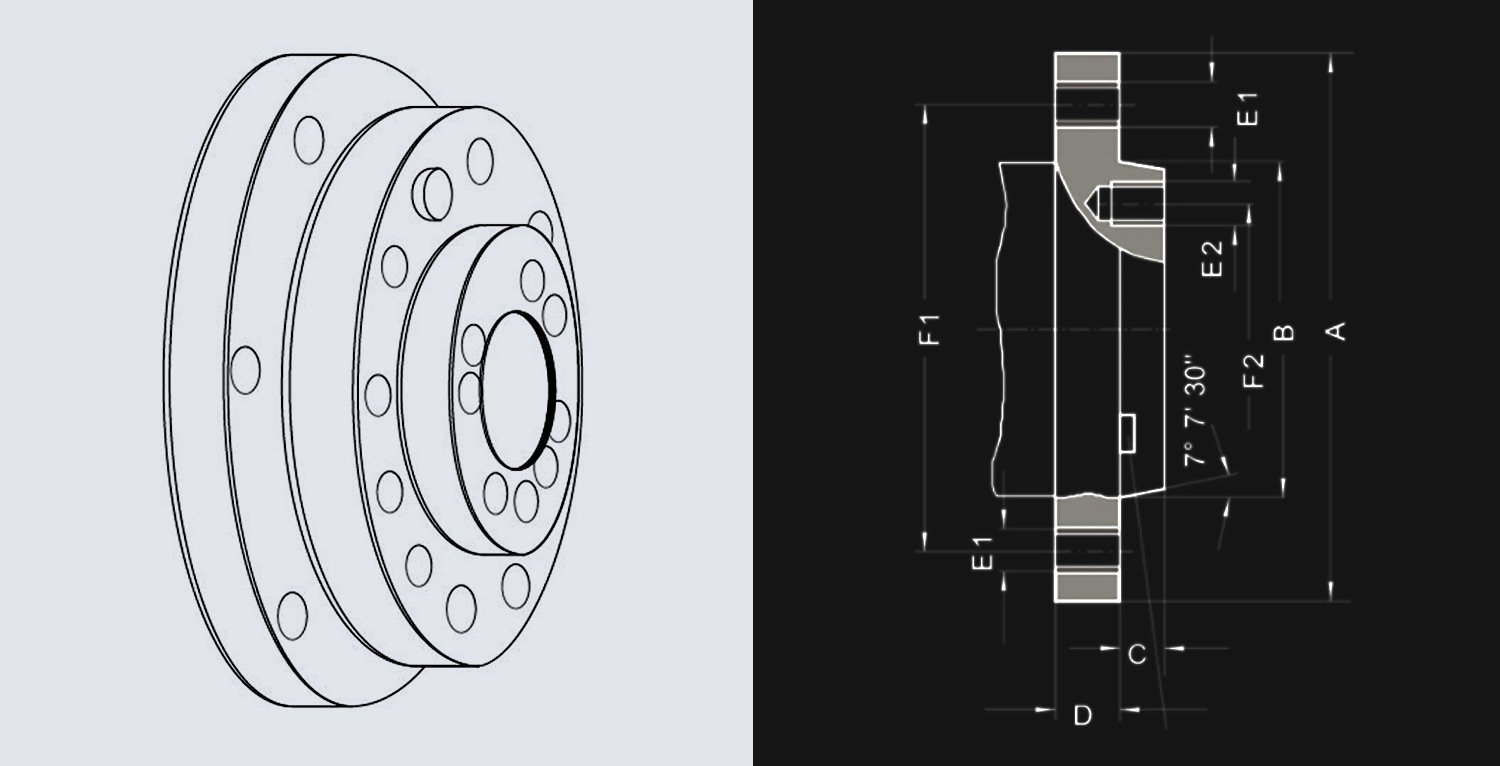
Type A2 short tapers have tapped holes on the outer-bolt circle but no holes on the inner-bolt circle. All chucks with an A2 mount can be installed on either an A2 or A1 spindle.
To determine A1 and A2 type and spindle size:
1. Measure the pilot diameter and length (B & C)
2. Measure the bolt circle diameter (F1 and F2) and diameter of the holes (E1 & E2)
3. Check the number of bolt circles (one for A2 mount or two for A1 mount)
| Spindle Nose | F1 (in.) | F2 (in.) | B (in.) | C max (in.) | Thread E1 = E2 UNC-3B |
|---|---|---|---|---|---|
| A-4 | 3.2500 | – | 2.5005 + .0005 | .4375 | 7/16-14 |
| A-5 | 4.1250 | 2.4374 | 3.2505 +.0005 | .5625 | 7/16-14 |
| A-6 | 5.2500 | 3.2500 | 4.1880 + .0005 | .6250 | 1/2-13 |
| A-8 | 6.7500 | 4.37500 | 5.50075 + .0005 | .6875 | 5/8-11 |
| A-11 | 9.2500 | 6.5000 | 7.75075 + .0005 | .7500 | 3/4-10 |
| A-15 | 13.0000 | 9.7500 | 11.251 + .001 | .8125 | 7/8-9 |
| A-20 | 18.2500 | 14.5000 | 16.251 +.001 | .8750 | 1-8 |
| A-28 | 25.5000 | 20.8750 | 23.001 + .001 | 1.000 | 1 1/4-7 |
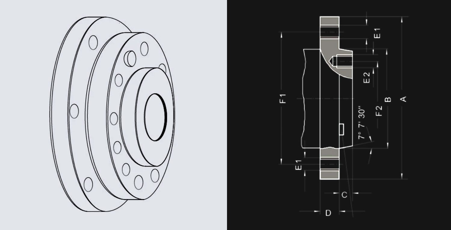
Type B1 short tapers have drilled holes on the outer-bolt circle and tapped holes on the inner-bolt circle.
Type B2 short tapers have drilled holes on the outer-bolt circle but no holes on the inner-bolt circle.
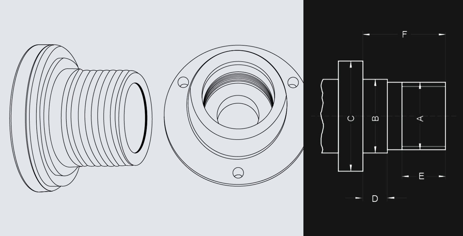
Type D1 Camlock mountings are often used to mount a chuck to larger, engine lathe spindles.
To mount a chuck, the lathe operator inserts the pins into the spindle and rotates the cam, pulling the pins snug to the chuck against the spindle. Each camlock pin features a D-shaped cutout on its body for locking the chuck onto the spindle nose via the cams. D1-3 to D1-4 chucks and adapter plates have 3 camlock pins, while D1-5 to D1-15 chucks and adapter plates have 6 camlock pins.
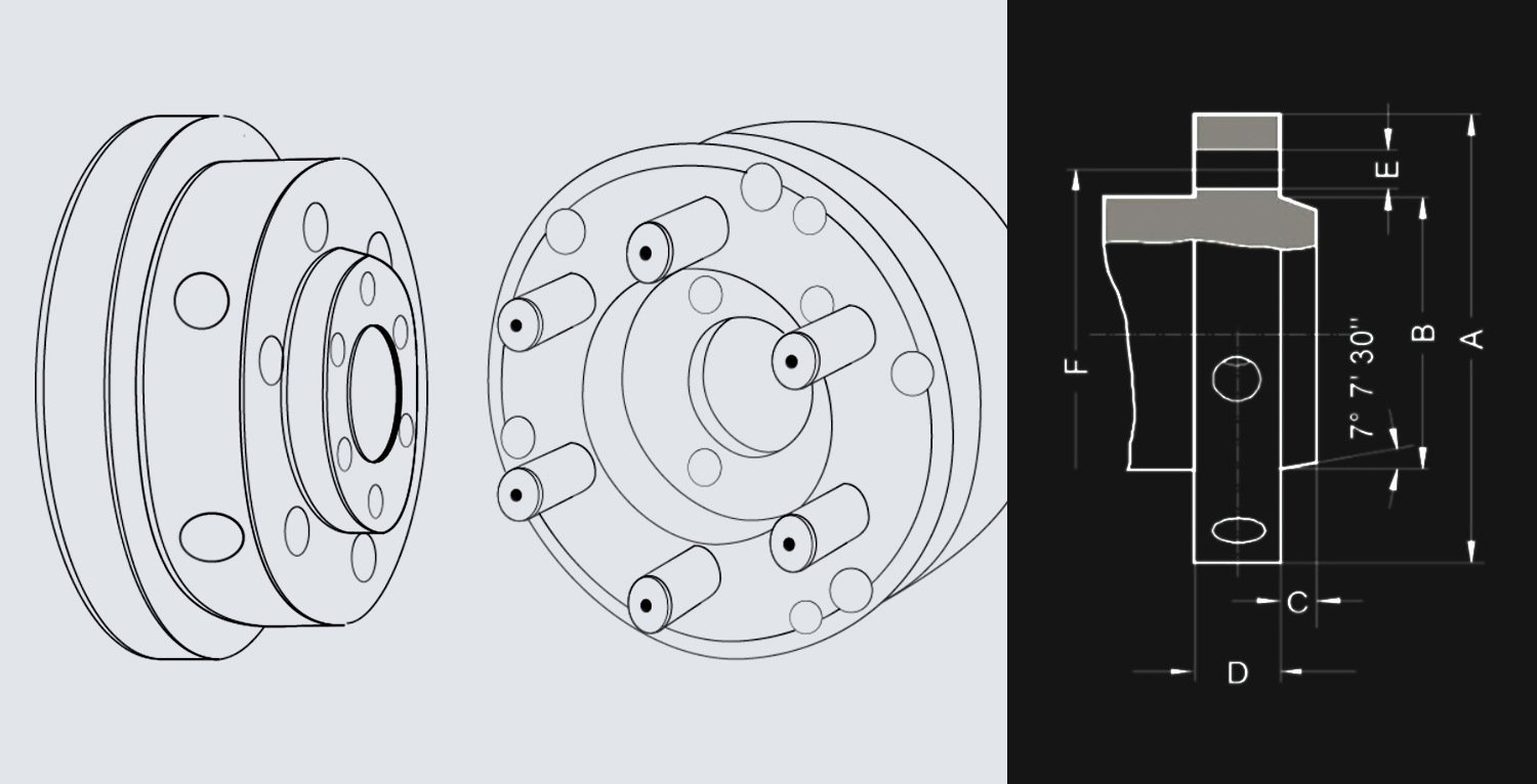
To determine the type and size of a D1 spindle:
1. Measure the pilot diameter and length (B & C)
2. Measure the bolt circle diameter (F)
3. Measure the diameter of the holes (E)
| Spindle Nose Size | A (in.) | F (in.) | B (in.) | C max (in.) |
E (in.) | Number of holes | Camplock stud diameter (in.) |
|---|---|---|---|---|---|---|---|
| D1-3 | 3.622 | 2.7820 | 2.1250 + .00025 | .4375 | .5937 | 3 | 9/16 |
| D1-4 | 4.606 | 3.2500 | 2.5005 + .0005 | .4375 | .6562 | 5/8 | |
| D1-5 | 5.748 | 4.1250 | 3.2505 + .0005 | .5000 | .8750 | 6 | 3/4 |
| D1-6 | 7.126 | 5.2500 | 4.1880 + .0005 | .5625 | 1.000 | 7/8 | |
| D1-8 | 8.858 | 6.7500 | 5.50075 +.0005 | .6250 | 1.125 | 1 | |
| D1-11 | 11.732 | 9.2520 | 7.75075 +.0005 | .6875 | 1.250 | 1 3/16 | |
| D1-15 | 15.866 | 13.0000 | 11.251 + .001 | .7500 | 1.375 | 1 3/8 |
Used for centering and locating fittings, long tapers feature a key for positive location and a flanged retention nut.
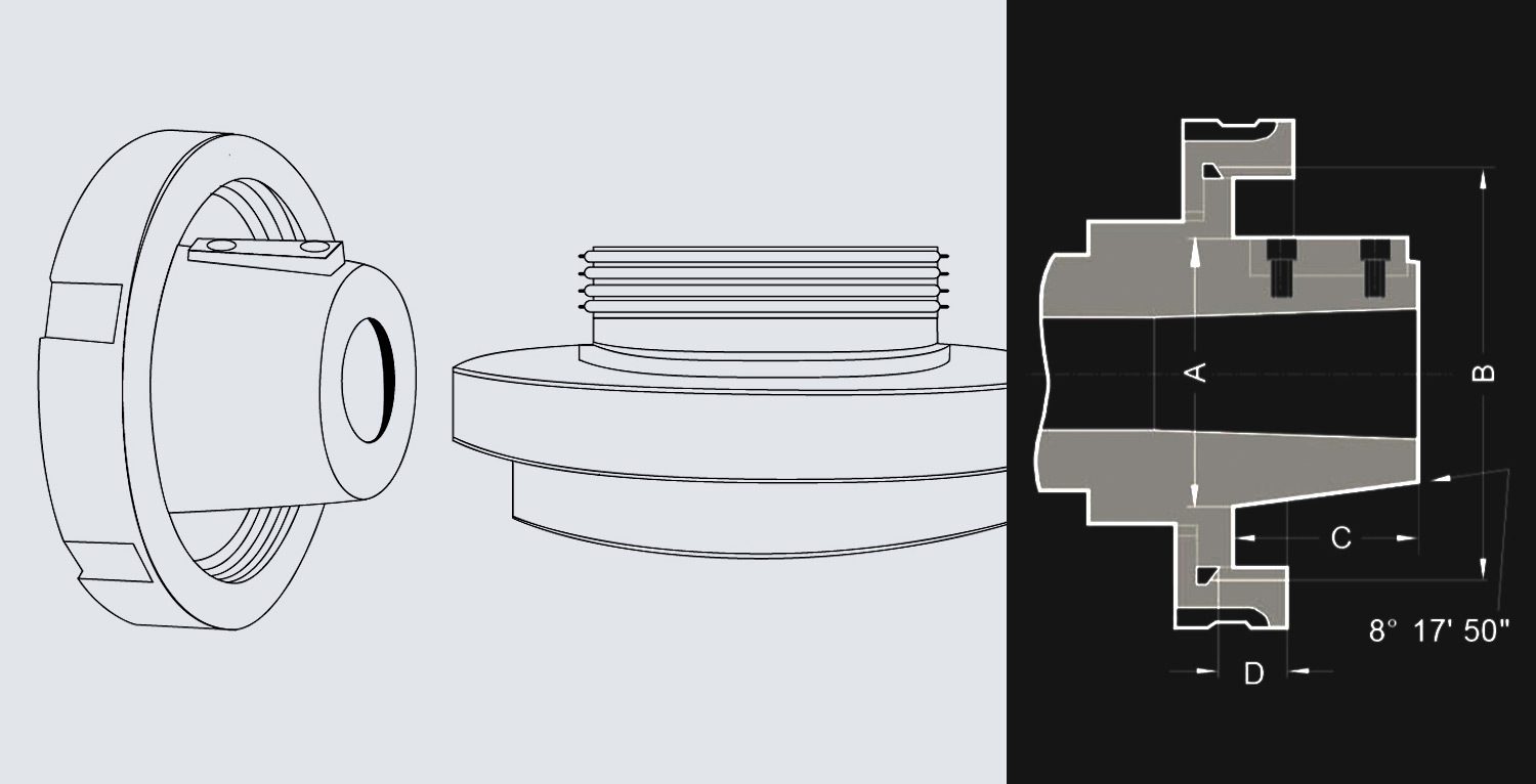
To determine the type and size of an L spindle:
1. Measure the pilot diameter (A)
2. Measure the length (C)
3. Measure the thread size (B)
| Spindle Nose |
Thread B | C (in.) | A (in.) | Key |
|---|---|---|---|---|
| L00 | 3 3/4″ – 6″ | 2 | 2.750 | 3/8 x 3/8 x 1 1/2 |
| L0 | 4 1/2″ – 6″ | 2 3/8 | 3.250 | 3/8 x 3/8 x 1 3/4 |
| L1 | 6″ – 6″ | 2 7/8 | 4.125 | 5/8 x 5/8 x 2 3/8 |
| L2 | 7 3/4″ – 5″ | 3 3/8 | 5.250 | 3/4 x 3/4 x 2 7/8 |
| L3 | 10 3/8″ – 4″ | 3 7/8 | 6.500 | 1 x 1 x 3 1/4 |
| A | B | C | D | E | F |
|---|---|---|---|---|---|
| M 20 | 21 | 30 | 6.3 | 10 | 20 |
| M 24 | 25 | 36 | 8 | 12 | 24 |
| M 33 | 34 | 50 | 9 | 14 | 30 |
| M 39 | 40 | 56 | 10 | 16 | 35 |
| M 45 | 46 | 67 | 11 | 18 | 40 |
| M 52 | 55 | 80 | 12 | 20 | 45 |
| M 60 | 62 | 90 | 14 | 22 | 50 |
| M 76×6 | 78 | 112 | 16 | 30 | 63 |
| M 105×6 | 106 | 150 | 20 | 40 | 80 |
Northland Tool & Electronics recently received a lathe spindle for repair from one of our customers who manufacturers surgical implants. The customer was experiencing unacceptable chatter on the surface finish of their parts, but was unable to troubleshoot the issue in-house. What’s more, all of our testing, vibration analysis, measurement of run out on critical surfaces, and motor testing showed the spindle to be within specification and healthy.
While test running the spindle with the tooling provided, our technicians started noticing odd frequencies showing on the vibration analysis, which pointed to mechanical looseness. We discerned that the tooling provided was indeed out of balance.
See how we troubleshot and addressed this issue to get this customer’s spindle back on track
If you have a lathe spindle that’s giving you issues, call or send a message to Northland Tool & Electronics. With over 40 years of experience repairing and rebuilding spindles for all kinds of applications, we have the knowledge and expertise required to troubleshoot and address most spindle problems. Schedule your evaluation today!